
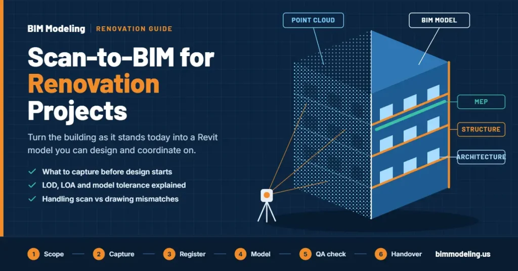
Pull the old drawings for almost any older building, and you will find a gap between the paper and the real thing. A wall got moved in the 1990s. A duct was rerouted above the ceiling. A slab isn’t quite level. None of this is unusual, but it matters the moment you start designing around it.
Scan-to-BIM for renovation projects deals with that problem. It turns measured site data into a structured model of the building as it stands today. Teams then use the model for design and construction. It works well only when the scope, coverage, tolerances, and limits are agreed before the scan starts.
Why Existing-Condition Information Matters Before Renovation
This guide walks through how to do that. You will see when to scan, what to capture, how the workflow runs, how to check accuracy, and what to do when the scan disagrees with the drawings.
The renovation team must consider one big question before they draw anything: ‘What is presently there?’ In the case of new buildings, the site is empty, so the design comes first and the building follows. On the contrary, in the case of renovation, the building is already there, and one must design to fit it.
That makes the quality of your existing-condition information a big deal, and the necessity for it is quite common. The European Court of Auditors reported in 2026 that about 75% of buildings in the EU are energy-inefficient. Many of those buildings will need work, and each one has its own history and its own changes. So teams keep running into the same problem: a gap between what the records say and what the building actually is.
Where old drawings can differ from the building
Old drawings still have value. They show the original intent, the grid lines, and a rough layout. The trouble starts with time. These drawings are changed from reality in a few common ways:
- Alterations that were never added to the drawing set
- Walls, floors, and ceilings that are not perfectly straight or level
- Services that were moved, added, or abandoned over the years
- Different parts of the building built in different decades, with different rules
- Revisions that were lost or never issued
These are possibilities, not guarantees. Some buildings match their drawings closely. The point is that you often can’t know until you measure.
Decisions affected by incomplete information
A gap on paper only becomes a problem when someone makes a decision from it. That is where the cost shows up, so it helps to look at which decisions are most exposed.
- Clearances: Will a new unit fit under that beam and still leave room to service it?
- MEP routing: Is there actually space above the ceiling for the new duct run?
- Openings: Does the new door or shaft line up with the structure around it?
- Quantities: Are the wall areas and floor areas you are pricing close to what is there?
- Sequencing: Can the trades work in the order you planned?
Each question depends on geometry. A model built from measured data gives the team something firmer to check against, which raises a simple question about what such a model is and what it contains.
What Is Scan-to-BIM for Renovation Projects?
Scan-to-BIM is a three-part process.
- A scanner or camera captures the space.
- The software lines up the captured data into one coordinate system.
- A modeler builds BIM objects from it.
BIM stands for building information modeling, and the result is a 3D model made of walls, slabs, columns, ducts, and other objects that carry information about this model.
Scan, point cloud, and BIM model: What is the difference?
These three terms get mixed up a lot, so here is how they differ.
- Scan: It is a process of collecting measurements on site, usually with terrestrial laser scanners, mobile LiDAR, or photogrammetry.
- Point cloud: It comprises millions of measured points that show the surfaces the scanner could see after registration. That means aligning the separate scans into one dataset.
- BIM model: A person interprets the points and builds objects from them. They decide what a wall is, what is a beam, and how each object should be classified and described.
When Should a Renovation Project Use Scan-to-BIM?
There is no single right moment. The best timing depends on where the project’s biggest risk sits and how much access you have. Three points in a project come up most often.
- Before concept and design development
Early scanning helps when BIM dimensions drive layout. If you are testing whether a new program fits inside an existing floor plate, you want real room sizes, floor levels, and ceiling heights, not approximate ones. A baseline model at this stage can also help with feasibility checks before the design is locked.
- After strip-out or selective opening-up
Some conditions only appear once finishes come off. Ceilings come down, walls open up, and services that were hidden become visible. A second capture at this point can record what was found. Strip-out isn’t always possible or needed, so treat this as an option, not a rule.
- During construction and at handover
Targeted rescans can verify the work which was done at place or identify any changes that happened during the construction process. At the time of delivery of the work, the (as-built) measurement allows the owner to keep a record of what has been accomplished. There are two different concepts: one is shown in the design baseline, which reflects the state of aspects before work has been done, and the (handover) record reveals the state after work has finished.
What Should Be Captured Before Renovation Design Starts?
Capture what the design and coordination decisions depend on. If a feature will not influence layout, fit, safety, or handover, it may not need to be in scope. That keeps cost and modeling time in check.
- Architecture and interior geometry
Start with the walls, floor and ceiling levels, openings, stairs, and room shapes. Add facade and roof geometry if the renovation touches them. Pay attention to places where floors or walls aren’t level or square, because new work has to meet them.
- Structure
Capture visible columns, beams, slabs, openings, and grid lines. A scan can show geometry, including visible irregularities. It can’t tell you what reinforcement is inside a slab or how much load a member can carry. Structural assessment stays with qualified engineers.
- MEP systems and plant
MEP means mechanical, electrical, and plumbing. Ceiling voids and plant rooms are often the tightest spaces in a building, so they deserve extra attention. Capture visible ducts, pipes, trays, risers, and equipment, and note the clearances needed for maintenance. Be clear about what is concealed or unreachable. Say so in the scope instead of assuming.
- Site, envelope, access, and context
Record entrances, external interfaces, extensions, and the roofline where they matter. Also note the practical limits: occupied rooms, locked doors, restricted hours, and areas that need special access.
The table below maps common elements to the reason for capturing them. Treat it as a starting point and adjust for your building.
| Element or area | Why capture it | Visibility and access | Critical dimensions | Likely owner | Exclusions or follow-up |
| Walls, floors, ceilings | Room geometry, levels, and area takeoffs | Usually visible; furniture can block | Wall positions, floor and ceiling heights, flatness | Architect | Note any areas blocked by furniture or storage |
| Doors and windows | Opening sizes and positions | Visible if rooms are accessible | Width, height, sill and head heights | Architect | Locked rooms need a return visit |
| Stairs, shafts, cores | Circulation and vertical routes | Often partly visible | Riser and tread, shaft size, landings | Architect and structural engineer | Sealed shafts may need access panels |
| Columns, beams, slabs | Structural geometry and openings | Visible unless covered by finishes | Grid positions, member sizes, slab levels | Structural engineer | Hidden members and reinforcement are not captured |
| Ducts, pipes, cable trays | Routing and clearance for new systems | Visible in open ceilings and plant rooms | Centerlines, elevations, spacing | MEP engineer | Services above ceiling tiles may need tiles lifted |
| Plant and equipment | Replacement fit and service access | Visible in plant rooms | Footprint, height, access clearance | MEP engineer | Equipment behind enclosures needs access |
| Facade and roof | Envelope upgrades and interfaces | Visible from inside or outside, depending on method | Openings, parapets, roof levels | Architect | Areas that need drones or lifts |
| Site and access | Logistics and external interfaces | Visible | Entrances, extensions, site limits | Project manager | Restricted or occupied zones |
Coverage and exclusions checklist
Before the survey starts, agree on a simple coverage log. It keeps everyone honest about what the scan did and did not reach.
Field | What to record |
| Area or floor | Which zone this row covers |
| Discipline | Architecture, structure, MEP, envelope |
| Access status | Open, partly blocked, locked, or occupied |
| Capture method | Laser scan, photogrammetry, or both |
| Known blind spots | Voids, tall shelving, locked rooms |
| Follow-up survey | Return visit, access panel, or opening-up work |
| Responsible reviewer | Person who signs off on this zone |
Laser Scanning vs Photogrammetry: How to Choose
Neither method is best in every case. Choose based on the decision the data has to support, the tolerance you need, and the site itself.
Method | Best-fit conditions | Strengths | Limits | Control and checks needed |
| Terrestrial laser scanning | Interiors, structure and MEP coordination, tight tolerances | Direct distance measurement, dense geometry | Line of sight needed; shiny or featureless surfaces can cause trouble | Survey control and registration checks |
| Mobile LiDAR | Large or long areas where speed matters | Fast coverage | Tolerance depends on the system and the setup | Verification against control points |
| Photogrammetry | Facades, heritage detail, visual records | Rich color and texture | Depends on lighting, image overlap, and calibration | Scale and control must be verified |
| Combined approach | Projects that need both geometry and visual detail | Pairs measured geometry with imagery | More planning and data to manage | A clear plan for how the datasets align |
When laser scanning fits
Laser scanning suits complex interiors, structural and MEP coordination, and any job where dimensional confidence matters. Plan for line of sight. Reflective or very plain surfaces can need extra care, and the scan still needs proper control.
When photogrammetry or a mixed approach helps
Photogrammetry is good at visual detail, such as facades and heritage features. Lighting, image overlap, and calibration all affect the result. It still needs control and verification when measurements matter.
Questions to ask before choosing
- What decision depends on this data?
- What tolerance does that decision need?
- Which areas must be covered, and which can be excluded?
- Are concealed conditions in scope or not?
- What model or file does the team need at the end?
The Scan-to-BIM Workflow for Renovation Projects
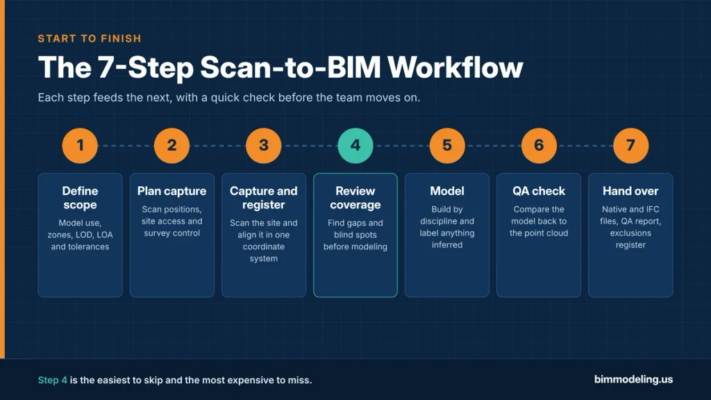
A scan is only useful if the surrounding processes are carried out in a reasonable sequence. The process detailed here consists of seven steps, from the initial planning discussion to the final transfer stage. Each step produces something the next one depends on, and each has a quick check before the team moves forward. Those checks are easy to skip when a deadline is close, and that is usually where problems start.
Here is how the work runs from start to finish.
- Define model use and survey scope
Write down what the model is for. List the floors and zones, the disciplines, the deliverables, the coordinate system, access limits, exclusions, LOD, LOA, and tolerances. Name the reviewers and say how you will accept the work. A vague scope leads to a vague model.
- Plan capture and site access
Plan scan positions or routes, overlap between positions, access windows, and control. Flag high-risk spaces such as congested ceilings and plant rooms. In occupied buildings, work out when each area can be reached.
- Capture and register scan data
Capture the site, then align the individual scans into one coordinate system using the agreed control. Run basic completeness checks before leaving the site if you can. Follow the equipment maker’s guidance for scanner settings instead of guessing.
- Review coverage before modeling
This step is easy to skip and expensive to skip. Look for occlusions, missing rooms, thin data, moving objects, and areas nobody could reach. Either schedule a return visit or record the limitation. Don’t let modeling start on data you already know has holes.
- Model from verified data
Model by discipline and by intended use. Label anything inferred, such as a pipe that disappears into a wall. Treat legacy drawings as a reference, not as truth. If a tool like Revit is used, keep the modeling rules consistent so elements are classified the same way throughout.
- QA against the point cloud
Compare the model back to the point cloud. Review sections and elevations, with extra attention on high-risk zones. Document deviations, exceptions, and review status so the checking leaves a trail.
- Package and hand over
Deliver the agreed native and open formats, views, model notes, a QA report, coordinate information, known limitations, and an exclusions register. The handover should tell the next person what the model can be trusted for and where it can’t.
Accuracy, LOD, LOA, and Model Tolerance Explained
People often ask, “How accurate is the model?” The honest answer is that it depends, and it depends on more than the scanner.
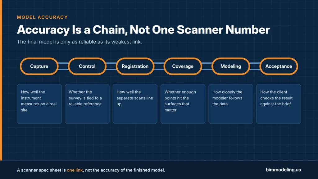
Accuracy is a chain, not a single scanner number
A scanner’s spec sheet has only one link. The final accuracy of a modeled element depends on several things working together. These factors are as follows:
- Capture: How well the instrument measures under real site conditions
- Control: Whether the survey is tied to a reliable reference
- Registration: How well the separate scans line up
- Coverage: Whether enough points hit the surface you care about
- Modeling: How closely the person drawing the element follows the data
- Acceptance: How the client checks the result against the brief
When an article quotes one millimeter number for everything, treat it with caution. That number may describe the instrument in ideal conditions, not the finished model.
LOD vs LOA vs tolerance
These terms sit side by side in a lot of specs, but they describe different things.
Term | What it describes | What it doesn’t describe | Who defines it | Source to check |
| LOD (Level of Development) | How developed a model element is and how far its information can be relied on | Measurement accuracy on its own | Project team, often using the BIMForum framework | BIMForum LOD Specification |
| LOA (Level of Accuracy) | The accuracy of the building documentation, covering measured and represented data | How detailed or complete an element is | Project team, often using the USIBD framework | USIBD Level of Accuracy |
| Tolerance | The deviation you will accept for a particular use | A universal rule for all elements | The project brief and the design team | Your own specification |
Both specifications get updated, so check the current version before you write them into a contract.
What Happens When the Scan and the Original Drawings Do Not Match?
It will happen, and how you handle it matters more than the fact that it happened. A mismatch that goes unnoticed until construction turns into rework, and rework is a real cost. A June 2026 report from the Tennessee Valley Authority’s Office of Inspector General looked at contractor rework on nuclear projects. In its background section, it notes that some data suggests mean rework can be as much as 10 percent of construction cost. That figure isn’t specific to scanning or renovation, and results vary by project. Still, it shows why catching a mismatch on paper costs less than catching it on site.
To handle each mismatch, follow the steps below.
- Log the discrepancy
Record the location or element, the source documents, what the scan shows, how confident you are, the likely impact, who owns the issue, the action, and when it closes. Here is a sample. The entries are made up to show the format, not real project data.
| ID | Location | Scan observation | Drawing reference | Status | Impact | Action owner | Closure |
| D-001 | Level 2, corridor | Ceiling duct sits lower than drawn | Sheet M-201 | Open | May reduce clearance for new tray | MEP engineer | Pending site check |
| D-002 | Level 1, east wall | Wall offset from drawn line | Sheet A-101 | Verified | Affects door position | Architect | Model updated, note added |
- Verify and route the issue
First check that the mismatch is real. Look at registration and coverage, and repeat the measurement if needed. Then send it to the right person, such as the architect or structural engineer. If the answer depends on what is behind a surface, selective opening-up or an extra survey may be the only way to know.
- Preserve the audit trail
Don’t quietly edit the model to match the old drawings. Keep a record of what the scan showed, what was accepted, and what is still unresolved. If someone asks six months later why a wall sits where it does, the log answers it.
Common Renovation Use Cases
The workflow of scan-to-BIM stays the same, no matter what the project type is. In the scenarios below, see how the core workflow stays the same, but the emphasis shifts with the job.
- MEP upgrades in occupied buildings
Focus on overhead routes, access, and clearances. Capture often has to be phased around tenants, so plan the sequence early and track which zones are done.
- Structural retrofit and adaptive reuse
The scan gives accurate geometry and visible interfaces. Judging whether the structure can carry new loads is a job for qualified professionals, and it needs information a scan can’t supply.
- Heritage buildings and irregular geometry
Old buildings often have curved walls, uneven floors, and detailed finishes. Balance the geometric record, visual detail, and how usable the model will be. Preservation rules may also shape what you can capture and how.
- Energy retrofit and envelope upgrades
Energy work is a big driver of renovation, but progress is slow in many places. A 2026 study from the University of Liège found that Belgium’s renovation rate, measured by residential building permits, has stayed around 1% per year since 2000, with deep renovations at only about 0.2% annually. For envelope work, a scan records facade, roof, and window geometry. Thermal imaging and energy analysis are separate methods that complement it.
Deliverables, Cost Drivers, and Timeline Factors
Once the technical side is clear, most teams ask about cost and time. There is no honest universal price or turnaround for Scan-to-BIM. What you can do is understand what moves both.
Typical deliverables to define
Start with what you will actually receive, and spell out each item in the brief.
Deliverable | What to specify |
| Point cloud | File format and how it is registered |
| Native BIM file | Software and version |
| IFC file | Only if open exchange is needed, and which IFC version |
| Drawings and views | Plans, sections, elevations, and discipline views |
| Model notes | How elements were modeled and what was inferred |
| QA report | Checks performed and results |
| Discrepancy and exclusions register | Open items, limits, and inaccessible areas |
| Coordinate setup | Origin, levels, and reference points |
At BIM Modeling, scan data and old drawings become editable Revit models. Our Scan to BIM and CAD to BIM work usually lands at LOD 200 to 300, and we state the tolerance we worked to so you know how far to trust the model. Native RVT files come in your Revit version, with Navisworks and IFC files when other teams need them. If you also need the field capture, we offer 3D laser scanning services.
What affects cost and schedule
- Building area and complexity
- Access, occupancy, and site hours
- Coverage needs and likelihood of rescans
- Number of disciplines
- Modeling scope, LOD, and tolerance
- File and format requirements
- Review cycles
- Deadline pressure
Why quotes need comparable scopes
If one provider prices a single floor and another prices the whole building, the numbers mean nothing side by side. Ask every provider to price the same areas, disciplines, tolerances, formats, exclusions, and acceptance checks. Then the differences in price reflect real differences in approach.
Request your free Scan-to-BIM estimate from our BIM coordinators today.
Get My Estimate Call (469) 498-9829How to Prepare a Scan-to-BIM Brief for a Provider
A good brief saves back-and-forth and prevents scope disputes. Cover these points in your scan-to-BIM brief:
- Project purpose and what the model will be used for
- Building address, floors, and existing plans
- Areas and disciplines in scope
- Access, occupancy, and safety rules
- Assumed capture method
- LOD, LOA, and tolerance requirements
- Coordinate system and levels
- Deliverables, formats, and software versions
- QA and acceptance criteria
- Known exclusions and inaccessible areas
- Timeline and key dates
- Privacy and security needs
- Who reviews and approves the work
- How changes to scope are handled
Conclusion
Good results come from the basics: a clear scope, enough coverage, the right level of modeling, real QA, and honest notes about what you don’t know. Start by asking which decisions the model has to support, and work backward from there.
Planning a renovation? Share the building areas, disciplines, intended model use, required deliverables, and access constraints so our team can help define an appropriate Scan-to-BIM scope.
Frequently Asked Questions
What is Scan-to-BIM for renovation?
It is a process that turns measured site data into a structured model of an existing building. Teams use the model to plan design, coordination, and construction work inside that building.
How accurate is a Scan-to-BIM model?
It depends on capture quality, control, registration, coverage, modeling, and the acceptance rules in the brief. Specify requirements using a current standard such as the USIBD LOA Specification instead of relying on one number.
Does laser scanning capture hidden pipes or structure?
No, not if they aren’t visible. A scan records surfaces it can see. To learn what is behind a finish, you need records, selective opening-up, or another survey method.
Do I still need the original drawings?
Yes. They give context and history. Just verify them where a decision depends on them.
What LOD do I need for an existing-building model?
It depends on how the model will be used and which elements matter. Define the requirement for each use instead of defaulting to the highest level.
How long does Scan-to-BIM take?
It varies by project. Access, building size, coverage, modeling scope, QA, and review cycles all play a part. A scoped quote is the best way to get a real estimate.
What files should be delivered?
That depends on your contract and how the model will be used. Ask for native files and open formats like IFC only where you need them.
Can Scan-to-BIM eliminate clashes or rework?
No, it can’t promise that. With a sound scope and proper QA, it can help the team spot geometry conflicts earlier. Results still depend on decisions and execution.
