Imagine your design team buried under stacks of dusty CAD drawings with millions of lines, countless X-refs, and layer names that look like someone had a bad pizza-ordering night. Despite the rise of Building Information Modeling (BIM), many architecture, engineering, and construction (AEC) firms still “live in CAD,” often because legacy projects, client habits, or simply inertia keep them tethered to 2D. But here’s the kicker: converting those CAD drawings into BIM isn’t just a trendy tech upgrade but a smart strategic move. Better collaboration, lifecycle value, and clash detection are just the tip of the iceberg. According to the 2024 State of BIM report, while over 90% of firms say they use BIM, only about 23% are applying it on most of their projects. This gap often exists because organizations still struggle with integrating old CAD data into their newer workflows.
So, what’s the fix? In this blog, we’re walking you through three realistic and battle-tested ways to convert CAD into BIM and when you should reach for each one. Whether you’re dealing with a simple office floor plan or a gritty as-built renovation, you’ll know what method to pick, why it matters, and how to do it well.
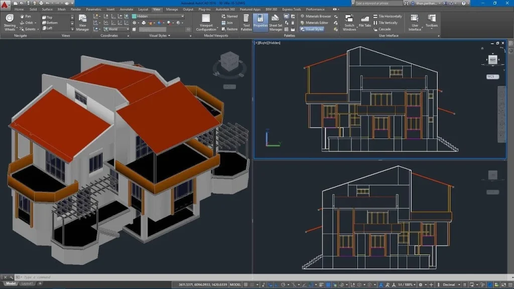
CAD vs BIM and Why Conversion Isn’t Easy
Let’s clear up what CAD vs BIM actually mean. People often treat them like two versions of the same thing, but they operate in completely different worlds.
Computer-Aided Design (CAD)
CAD, at its core, is drafting. You draw lines. You arrange shapes. You stack layers however the project (or the last person who touched it) decided they should be stacked. A line in CAD doesn’t know anything about itself. It won’t tell you what material it represents or whether it belongs to a wall or just someone’s forgotten detail. It’s geometry—sharp, simple, obedient, and completely unaware.
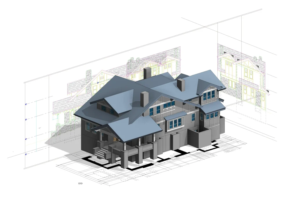
Building Information Modeling (BIM)
BIM behaves nothing like that. It uses actual building components as its building blocks. A wall in BIM isn’t a thick polyline; it’s an object with height, thickness, materials, maybe even energy data if someone bothered to add it. The model carries information with it—metadata, relationships, behavior. It’s part drawing, part database, part living thing.
This difference is exactly why conversion between the two isn’t some mystical “open file → instant BIM” shortcut. CAD doesn’t secretly store the meaning of its lines. It can’t whisper to Revit, “Hey, that’s a door over there.” A BIM tool looks at a CAD drawing and sees… lines. Nothing more. Any intelligence has to be added, interpreted, or reconstructed.
And then there’s the structural contrast: CAD spreads work across separate files—plans in one, sections in another, strange detail drawings living in their own little universe. BIM wants everything gathered in one coordinated place. Change a door size in BIM and that update flows everywhere. Change a door in CAD and you hope everyone else remembers to adjust their sheets too. Sometimes they don’t.
Collaboration shifts dramatically as well. CAD can feel like sending emails back and forth. BIM feels closer to everyone sharing the same workspace, noticing issues early because the model actually understands what exists where. That’s why clash detection works in BIM—because the software knows a duct and a beam aren’t supposed to claim the same spot.
So yes, the conversion matters. But no, it’s not automatic. CAD is quiet. BIM is structured and talkative. Turning one into the other is a process, not a button.
The Essential Preparation Steps
Before the actual conversion, there’s a bit of groundwork that absolutely has to happen. Skipping this part only guarantees frustration later.
Decide Your Target LOD
You can’t begin without knowing how detailed the final BIM model needs to be. This is the LOD. Level of Developement ranges from 100 all the way to 500. At LOD 100, you’re basically modeling shapes and rough placements and by the time you reach LOD 500, you’re describing actual, real-world, verified components. People sometimes underestimate how much this decision affects everything else, but it does. If your deliverable is only meant to show general layout, don’t waste time building hyper-accurate families. If the client expects fabrication-ready info, then the model has to be rebuilt with much more intention. The target LOD becomes the map for the entire conversion.
Collect & Audit All CAD Source Files
Next step: gather every scrap of information the project ever spawned. Not just the DWGs. Bring in PDFs, Xrefs, any stray 3D solids, the occasional mysterious model someone exported ten years ago, and even point clouds if they exist. Throw them all onto the table. You need the complete picture, even if some files turn out to be junk.
Then start checking the basics like scale, units, coordinate system, and any sneaky rotated views. CAD files love surprises. What looks aligned sometimes isn’t. What appears consistent often hides tiny mismatches. And yes, this matters later, because BIM models don’t tolerate sloppy origins or odd rotations.
Once that’s sorted, it’s cleanup time. Remove layers no one uses. Break apart odd blocks that refuse to behave. Purge the file so it stops carrying dead references. Standardize naming so people don’t have to guess what “L-WALL-OLD??” means. It’s not glamorous work, but if you skip it, the conversion becomes a mess.
Stakeholder & Deliverable Plan
This part is oddly overlooked. Someone needs to ask, “Who actually needs what from the BIM model?” Architects, structural engineers, and MEP teams all care about different pieces. If an engineer needs specific duct data, that changes your requirements. If a client only wants a basic space model, the workload drops dramatically. Without this conversation, the project ends up bloated or incomplete.
Define Acceptance & QA Checks
Before modeling begins, set the rules for what “done” looks like. You don’t want chaos later. Define the checks: geometry accuracy, naming consistency, element classification, whatever the team relies on. This becomes the benchmark you refer back to when people start asking whether something is ready or not. It also prevents the familiar “we thought you were doing that part” argument.
Method 1: Manual Rebuild Inside BIM (the Gold Standard)
Renovations, as-built conditions, complicated MEP layouts, situations where the geometry has to be right; this is where manual rebuilding earns its title as the gold standard.
When to Use This Method
If the project needs deep detail, use this. If the model will be handed off to contractors, fabricators, facility managers—again, use this. Data integrity matters a lot in those scenarios, and automated tools rarely understand the nuance of old CAD drawings. They guess, and guessing creates chaos. A manual rebuild avoids that whole mess.
Workflow (Step by Step)
1. Import or Link the CAD Plans as an Underlay
Start by pulling the CAD drawings into your BIM software, but keep them on a leash. Link them instead of importing them as editable objects. You want them as a reference, a ghost outline. Don’t let the CAD lines become part of your model; they bring too much baggage with them.
2. Set Up a Proper Project Template
Before touching any geometry, load your template. Family libraries, shared parameters, grids, levels, whatever your team always uses. A good template feels like a silent assistant that organizes your entire project before you even begin modeling.
3. Recreate the Building Using Native BIM Objects
This is the real work. Walls become actual walls. Floors become actual floors. Doors, windows, columns, beams, everything gets rebuilt with native elements instead of traced polylines. It’s slower, sure, but you end up with a model that behaves like a building rather than a stack of lines pretending to be one.
4. Add Metadata
Once the geometry looks right, start layering in the information. Asset tags, manufacturer details, performance values, all the boring-but-important data that makes BIM valuable. This is usually the part where someone finds missing info and has to chase down the original drawings or ask the client for clarification. It’s normal.
5. Run Iterative QA Checks
Don’t wait until the end to test accuracy. Check dimensions. Flip to sections. Zoom in on corners where weird geometry likes to hide. Run clashes, especially MEP vs structural. Fix what needs fixing, then run the checks again. A manual model improves every time you loop through this cycle.
6. Deliver the Model According to the LOD Requirements
When everything aligns with the LOD spec, package the model. Export schedules, COBie sheets, whatever the deliverable list demands. If the earlier steps were done well, this part is surprisingly painless.
Start A Pilot Conversion Today With Us
Contact UsPros and Cons of This Method
Pros
- Maximum control over every element.
- Clean data structure from the ground up.
- Reliable path to high-LOD deliverables.
- Fewer surprises later because humans made the decisions, not algorithms.
Cons
- Slow. No way around it.
- Requires skilled BIM modelers who know what they’re looking at.
- More expensive upfront, though it often saves money by avoiding rework.
Tools & Tips
Most teams use Revit for this method, but ArchiCAD and Tekla fit well depending on discipline and region. A solid template helps a lot. So does a modeler who has patience and a good eye for tiny inconsistencies that CAD files like to hide.
Method 2: Semi-Automated Conversion (The Recommended Compromise)
Not every project deserves a full manual rebuild. Sometimes the timeline is tight. Sometimes the budget is thinner than expected. And sometimes the drawings are “meh” rather than catastrophic. That’s where semi-automated conversion sits with half machine, half human, and surprisingly effective when used in the right situations. It hits a comfortable middle ground, especially for LOD 200–300 work where you need things accurate enough without spending weeks rebuilding every wall from scratch.
When to Use This Method
This approach fits a lot of real-world scenarios: office remodels, mid-rise developments, tenant improvements, medium-complexity MEP layouts. If the goal is a functional BIM model that coordinates well, but doesn’t require microscopic detail, this method usually gets the job done without burning through half your modeling team’s sanity.
What “Semi-Automated” Actually Means
Think of it as a little production line. The software tries to identify walls, doors, slabs, and other basic elements. Then a human steps in and fixes what the software misunderstood. Some tools pull off pretty impressive feature recognition; others get confused by random hatch patterns and start labeling everything as a wall. So it’s not a fully automated miracle amd more like a helpful assistant that works fast but needs supervision.
Workflow (Step by Step)
1. Preprocess the CAD Files
Before running anything through a converter, clean the CAD files. Strip away the noise. Layers that serve no purpose can be removed. Blocks that behave strangely might need exploding. Old inconsistent lineweights or oddly named layers get standardized. The cleaner the input, the less the conversion tool guesses wrong.
2. Run the Conversion Tool or Plugin
This is where the automation kicks in. The tool scans the drawing and tries to identify building elements like walls, openings, slabs, columns. Some tools do a fair job if the CAD is neat. Others struggle, especially with messy legacy drawings that look like they were assembled by five different interns over ten years. Still, the machine gets you a rough first draft far quicker than manual tracing.
3. Human Review and Correction
Once the machine has taken its shot, a modeler goes in and fixes the weirdness. A wall placed where a countertop used to be. A door that opens into the void. A slab that looks like it melted into a stair. This step can range from quick to frustrating, depending on the quality of the original CAD.
4. Enrich the Model with Data
After the geometry is stable, add the essentials: parameters, types, classification codes, maybe some basic material data. Nothing too deep, just enough for schedules and coordination. This keeps the model useful without overloading it with unnecessary detail.
5. QA and Final Delivery
Check dimensions. Run a few clash tests. Make sure nothing drifted off the grid. Once the model behaves and the major components align with the drawings, wrap it up and deliver.
Pros and Cons of This Method
Pros
- Much faster than a full manual build.
- Helps control costs without sacrificing too much accuracy.
- Fits many standard commercial and residential projects.
- Good balance between automation and human judgment.
Cons
- Automatic classification can get creative in all the wrong ways.
- Still requires manual cleanup and careful review.
- Not suitable for high-LOD or highly regulated projects.
Method 3: Fully Automated / AI & “Modelification” Tools
This is the fast-food version of CAD-to-BIM. You press a button, the software churns for a moment, and a model pops out the other side. It’s not gourmet, but it’s quick and sometimes exactly what you need. Early feasibility studies, rough massing exercises, and initial coordination checks; these are the situations where fully automated conversion makes sense. When the goal is simply to get something shaped like the building into a BIM environment, LOD 100–200 is usually enough, and this approach fits that tier nicely.
When to Use This Method
Use it when detail doesn’t matter yet. When you just want a model to communicate intent or test some early ideas. Or when you’ve been handed a mountain of inherited CAD files and the client only needs a rough, scalable BIM base. Full automation is great at making “something” quickly. Just don’t expect it to nail every wall thickness or interpret stair geometry that was drawn in the 90s.
How It Works
The idea is simple: the tool looks at 2D lines or 3D solids and tries to guess what they represent. Some tools follow strict rules (“two parallel lines with a certain gap = wall”). Others use machine learning to detect patterns or architectural conventions. They chew through DWGs, DXFs, sometimes even point clouds, and try to turn that chaos into actual parametric objects. The good ones are impressive; the weaker ones produce models that feel like a rough sketch built by someone who only skimmed the drawings.
Workflow (Step by Step)
1. Input the Source Data
Feed the tool whatever you have. These can be DWGs, DXFs, occasionally a point cloud. The cleaner the input, the happier the tool, but full automation can tolerate messier files than the semi-automated path.
2. Run the Automated Conversion Engine
Click the button, start the process, and wait. The engine analyzes geometry, tries to identify patterns, and starts mapping those shapes to BIM objects. This part usually happens faster than you expect. Sometimes too fast, leaving you wondering what exactly the tool “thought” it saw.
3. Let Auto-Classification Propose a Model
The software spits out a candidate model: walls, slabs, roofs, openings, sometimes even rooms if the tool is clever enough. It’s rough. It’s often missing pieces. But it’s a start.
4. Perform Human QA
Even the best automated tools need human eyes. A quick walkthrough usually reveals oddities such as walls shifted a few inches, geometry interpreted incorrectly, strange phantom objects floating around. Fix the critical issues, delete the nonsense, and keep the helpful structure.
5. Use the Output as the Final or as a Base for Refinement
For feasibility and massing, the auto-generated model might be “done.” For anything more serious, the model becomes a starting point. You refine, replace objects, add structure, and push it toward whatever LOD the project needs next.
Pros and Cons of This Method
Pros
- Easily the fastest option.
- Works well for early-stage modeling or bulk conversions.
- Can handle large volumes of drawings without burning through team hours.
- Good starting point for later refinement.
Cons
- Automatic interpretation can be wildly inaccurate on complex or messy geometry.
- Missing elements are common.
- Requires human QA before anyone trusts it.
- Not suitable for detailed or critical deliverables
Choosing the Right Method
The following table will help you assess and make and informed decision while choosing the method to convert the drawings.
Decision Matrix
| Project Type | Target LOD | Time vs Cost | Recommended Method | Typical QA Steps |
| Small, simple, schematic designs; conceptual studies; early feasibility | LOD 100–200 | Fast turnaround, minimal cost | Method 3: Fully Automated / AI Tools | Quick geometry scan, spot-check walls/rooms, remove obvious misclassifications, verify levels |
| Medium-size office projects; renovations with limited detail; moderate coordination needs | LOD 200–300 | Balanced speed and cost | Method 2: Semi-Automated Conversion | Check element alignment, confirm wall types, validate major openings, run basic clash tests |
| Complex buildings; hospitals; as-built conditions; projects with strict standards | LOD 300–500 | Highest cost and longest timeline | Method 1: Manual Rebuild | Full dimensional verification, multi-view checks, detailed clash detection, parameter validation, metadata QA |
Conclusion
Three ways to turn CAD into BIM.
- Manual rebuild that is slow, precise, and high detail.
- Semi-automated that is software guesses, humans fix, middle ground.
- Fully automated, that is fast, rough, and early-stage.
Pick based on LOD, budget, timeline, and what data really matters. Prep first. Run a pilot. Document the steps. Check your work. One messy CAD file can wreck a week of modeling if you skip this. So don’t guess! Test a small project. See how it behaves. Learn the quirks. Then scale. Your next BIM model will thank you.
