An HVAC system is the backbone of indoor comfort in buildings. It’s responsible for keeping inhabitants warm in winter, cool in summer, and breathing easy year-round. We can say that the HVAC system is the lungs in the building that bring in fresh air, filter it, and heat or cool it as needed. Before their best performance, the system design comes; they must meet the local standards, like ASHRAE 90.1 for energy efficiency and ASHRAE 62.1 for ventilation.
In this blog, we will explore HVAC basics, how a system actually works, and why using BIM (Building Information Modeling), especially with tools like Revit, makes designing these systems way more efficient. Let’s start!
What Does HVAC Stand For?
HVAC stands for Heating, Ventilation, and Air Conditioning. In simple terms, that means it’s the system that warms, cools, and circulates air in a building.
- Heating comes from a gas furnace, electric boiler, or heat pump.
- Ventilation means exchanging bad indoor air with fresh outdoor air.
- Air conditioning means removing heat and humidity, using refrigerant cycles, to cool things down.
Together, these functions maintain the building’s temperature, humidity, and indoor air quality (IAQ).
Major Types of HVAC Systems
HVAC systems come in many types, each suited to particular buildings:
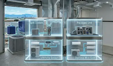
Split System
It has separate indoor and outdoor units. The indoor unit, which includes a furnace or air handler, conditions air; the outdoor unit, which contains a condenser or heat pump, handles cooling. This is common in US homes and small offices.
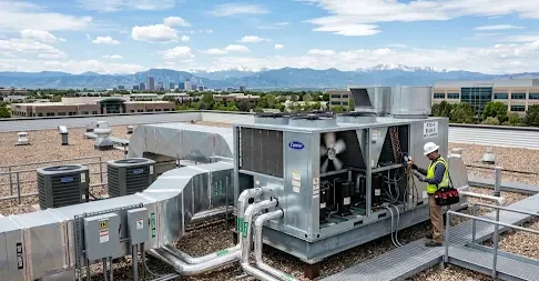
Packaged Unit
It is an all-in-one unit and is often found on a roof or slab. This type of system contains both heating and cooling coils in one box and is used in commercial buildings or homes without basements.
VRF/VRV System
It stands for Variable Refrigerant Flow, and is also known as the Variable Refrigerant Volume system. This type of HVAC system is like a multi-zone heat pump system: one or more outdoor units serve many indoor units. Each indoor unit can have its own thermostat. VRF systems vary compressor speed to match loads, making them very energy-efficient in large or multi-zone buildings.
Ductless Mini-Split
It is a variant of a split system without ducts. In this system, one outdoor compressor connects to multiple indoor wall or ceiling units, each handling its own zone. This type is great for retrofits, additions, or rooms without ductwork. Each head provides heating or cooling and is controlled independently.
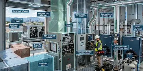
Key Components of an HVAC System
Every HVAC setup is built from a few key parts. Here are the major components and what they do:
Furnaces/Boilers
They burn fuel, which includes gas & oil, or use electric heat to warm air or water. Simply put, they are the heat source in most systems.
Air Conditioners & Chillers
Unlike furnaces or boilers, air conditioners and chillers remove heat and cool air or water. Central AC units cool refrigerant in coils; chillers cool water that then cools air. This means both handle the cooling load in the building.
Heat Pumps (Optional)
Heat pumps move heat between indoors and outdoors. In warm weather, it cools like an AC, and in cold weather, it heats by pulling heat from outside.
Air Handlers (AHU)
AHUs blow air through the system. It has a fan and conditioning coils that distribute warm or cool air through the ducts.
Ductwork & Diffusers
They are the channels for airflow. Ducts carry conditioned air to rooms and return air. Registers and diffusers at the room end spread the air evenly.
Note: Proper sealing and layout of the room are critical for the efficiency of ducts and diffusers.
Thermostats/Controls
They work the same in an HVAC as a brain does in a human body. Sensors and thermostats monitor temperature, and sometimes humidity or CO₂, and turn the system on/off or modulate components to stay at setpoints.
Ventilation Fans & Dampers
Ventilation fans and dampers bring in outdoor air and expel bad indoor air. Fans push air through ducts; dampers control flow rates. Proper ventilation keeps IAQ standards (ASHRAE 62.1) in check.
Filters & Humidity Controls
Air filters remove dust and pollen to keep the air clean inside the building. And humidifiers or dehumidifiers adjust moisture. Together they protect equipment and improve comfort.
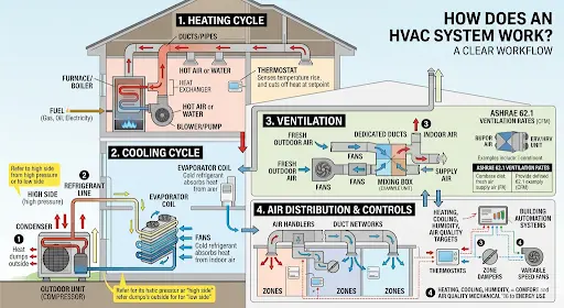
How Does an HVAC System Work?
An HVAC system operates in coordinated cycles. Let’s break it down step by step:
Heating Cycle
If you need warmth, fuel, such as natural gas, oil, or electricity, powers the furnace or boiler. That device heats air (with a heat exchanger) or hot water. A blower or pump then pushes that hot air or water through the ducts or pipes into rooms. The thermostat senses the temperature rise and cuts off heat once the setpoint is met.
Cooling Cycle
In cooling mode, the system uses a refrigerant cycle, like an AC unit. The compressor, which is an outdoor unit, squeezes refrigerant on the high side of the system, giving high pressure. Heat is dumped outside at the condenser. The cold refrigerant then flows inside to the evaporator coil, where it absorbs heat from indoor air, thus cooling the air—the warm refrigerant returns outside to repeat the cycle.
Note: The terms “high side” and “low side” refer to the pressure zones in a split system; see our guide What are the high side and the low side in HVAC for details.
Ventilation
Good IAQ means fresh air is crucial. Fans pull in outdoor air and exhaust indoor air through dedicated ducts. Systems often meet ASHRAE 62.1 ventilation rates by adding a certain cubic feet per minute (CFM) of outside air per person/area. Fresh air can be mixed into the supply air stream or provided via special ERV/HRV units. Proper ventilation prevents stuffy air and dilutes contaminants.
Air Distribution & Controls
Whether heating or cooling, air handlers and duct networks distribute the conditioned air. Thermostats and building automation systems control which zones get conditioned air and when. Modern systems might have zone dampers or variable speed fans to fine-tune comfort per area. In summary, all these pieces work together to meet the heating, cooling, humidity, and air quality targets of the building. The mechanical components cycle on/off or modulate to balance comfort and energy use.
Compliance: HVAC System US Codes & Standards
In the U.S., HVAC design exists under a bundle of codes and standards. Key ones include:
ASHRAE 90.1 (Energy Code)
This sets minimum efficiency requirements for equipment and envelope. Modern BIM tools, like Revit with Insight, can export energy models (gbXML) to check 90.1 compliance. Many firms run energy compliance checks directly from the BIM model.
ASHRAE 62.1 (Ventilation)
This standard specifies how much outdoor air per person or area is needed. BIM lets you document actual outdoor air flows by room or zone to prove compliance.
IMC/IECC
These are the International Mechanical and Energy codes that incorporate ASHRAE and may add local amendments.
LEED/Green Codes
These codes are about accurate HVAC models with zones and equipment that support LEED credits, like modeling performance, and local green building programs.
Why Use BIM Modeling for HVAC Systems?
BIM (Building Information Modeling) is a game-changer for HVAC design. In a BIM environment, like Revit, all mechanical equipment, ducts, and pipes are 3D objects with data attached. That means your HVAC layout is not just lines on a drawing, but an integrated model. Here’s why BIM is so valuable for HVAC systems:
Clash Detection & Improved Coordination
Since architects, structural engineers, and MEPs work in one model, the software can automatically find where ducts cross beams or pipes hit sprinklers. This catches clashes early, preventing last-minute field rework.
Capacity Analysis & Accurate Load Calculations
BIM data can drive load calculations. You can use Revit’s built-in tools or export gbXML to size equipment precisely for the actual building geometry. This means you’re not guessing a furnace size in the dark; the model’s zones and walls provide exact loads.
Automated Consistent Documentation
Because the BIM model is the source of truth, any move of a duct or change of a pipe size instantly updates all plan views and schedules. This means that you don’t have to hunt through dozens of sheets to fix an error. This consistency also means that if you have to submit drawings or schedules for permits, they reflect the true modeled system.
Cost & Material Reduction
Every duct and pipe has a length and size in the model, so you get exact material take-offs. You’ll waste less by ordering what the model shows rather than guessing. Also, BIM can cut change orders dramatically simply by doing more design work virtually.
Lifecycle Data
BIM isn’t just for design; however, it becomes a digital twin. Equipment parameters, such as capacities, model numbers, and maintenance info, stored in families can feed facility management. Years later, you or the building operator know exactly what AC model was installed and when it was last serviced.
Simply put, BIM turns HVAC design from a set of 2D drawings into a cohesive data-rich model. We can see the whole system in 3D, coordinate with other trades, and even simulate performance.
The Standard BIM Workflow for HVAC Design
1. Project Setup
Experts start Revit with an MEP (Mechanical) template, and switch units to US customary (feet, inches) if needed.
2. Link Architecture/Structure
Then, they insert the architect’s model as a Revit link and use Copy/Monitor to align levels and grids. After that, they pin the linked model so it doesn’t move.
3. Define Views/Levels
This is followed by creating HVAC-specific plans, which include ceiling and equipment plans. The team next copied the building’s levels into the HVAC model. This ensures the ducts and pipes are placed on the right floor elevations.
4. Configure Mechanical Settings
In Manage to MEP Settings, they set the default duct pressure classes, pipe sizing rules, materials, and offsets. For example, you might pick a 0.2” gauge steel duct at medium pressure by default, so Revit knows how to size it.
5. Create Spaces and Zones
Further, they place space objects in every conditioned room. Then group them into HVAC zones (e.g., a VAV zone per floor). These zones provide data for heating or cooling loads and ventilation requirements. In Revit 2022+, this also creates analytical spaces for Systems Analysis.
6. Place Equipment & Terminals
Next comes inserting mechanical equipment families (AHUs, rooftop units, chillers, boilers) in the model, where they go (usually mechanical rooms or rooftops). Then, teams place air terminals, which include supply and return diffusers or registers in ceilings or walls in each room, specifying design airflow (CFM).
7. Route Ductwork & Piping
After that, they assign air terminals to supply or return systems. They use the duct tool to draw ducts between units and diffusers. The software auto-fills elbows and tees. They do the same with piping (hot/chilled water loops) using the Pipe tool. Each segment has a system type and can be auto-sized.
8. Sizing and Analysis
Professionals use Revit’s duct or pipe sizing tools to finalize diameters based on friction rates or static pressure limits. They run heating or cooling load calculations (Revit’s built-in or export to, say, Trace 700) as well as adjust equipment capacities as needed.
9. Coordination
After sizing and analysis, teams link the structural, architectural, and other MEP models. They run clash detection in Revit or Navisworks to catch interferences and fix any clashes by rerouting ducts or adjusting structures early.
10. Documentation
Next comes the generation of sheet drawings, which include:
- Plans
- Sections
- Isometrics
- Schedules.
Because the model is parametric, if something moves, all drawings update. Fabrication data, including sheet metal spools and pipe spools, can even be exported.
Note: At each step, BIM 360 or another CDE lets teams work together smoothly. Everyone, including architects, engineers, and contractors, is virtually in the same room, even if they’re remote. Therefore, every one of them relies on BIM coordination services from the experts in the market, benefiting from their expertise at the highest level.
HVAC System Modeling With Revit
Let’s get hands-on with Revit, since it’s the most common BIM tool for HVAC.
Project Setup in Revit MEP
1. Mechanical Template & Units
Start Revit and choose a Mechanical (HVAC) template. This auto-loads duct, pipe, and equipment families. Set Project Units (Manage > Project Units) to US Customary (feet, inches).
Improve HVAC coordination with BIM—get started today.
Contact Us2. Link Building Models
Under Insert, link the architect’s and structural models. Check the box for “By shared coordinates” if you have them. Pin those links so they can’t move by mistake. Now use Copy/Monitor → Levels to grab the building levels from the architect. This ensures your floors align perfectly.
Note: Do the same for grids if needed.
3. Create HVAC Views
Right-click levels to make new floor plan views, e.g., HVAC Plans, and reflected ceiling plans (RCPs). Adjust view ranges on RCPs so ducts near the ceiling show up.
4. Configure MEP Settings
Go to Manage → MEP Settings. Here, check the followings:
- Default duct pressure class (e.g., medium-static)
- Default pipe specifications (e.g., Class 160 PVC)
- Sizing rules (friction rate or velocity limits)
Also set the default offsets (e.g., ducts are 6″ below the ceiling) under “Duct & Pipe Settings”.
5. Create Spaces and Zones
Turn on your HVAC plan, and under the Mechanical tab, place Space elements in every room. In each Space, enter occupancy counts or area per person so Revit knows ventilation needs. Then use Spaces to define HVAC zones; one zone might serve several adjacent rooms.
Modeling HVAC Components or Families
Now, the actual equipment and ducts go in:
6. Place Mechanical Equipment
Load or select families for AHUs, boilers, chillers, pumps, VAV boxes, etc. Stick them in the right rooms.
Pro Tip: Use manufacturer BIM content or Revit’s library.
For example, drop an AHU family into the mechanical room. Each family has connectors for airflow or water. Revit uses those connectors to join ducts or pipes.
7. Insert Air Terminals
In each conditioned room, place supply diffusers or grilles and return grilles. Set their flow rates (e.g., 500 CFM for a big office). These go into ceilings or walls. Be sure to assign them as Supply or Return air terminals so Revit knows which system they belong to.
8. Draw Ductwork
Use the Duct tool to draw from the AHU to each supply terminal. Revit will auto-connect and size segments. You can switch shapes, e.g., rectangular vs round, on the fly. The software auto-inserts elbows, tees, and transition fittings as you route.
9. Lay Out Piping
If you have chilled or hot water equipment, use the Pipe tool similarly. Draw supply or return loops from chillers or boilers to AHUs or fan coil units. Again, Revit will connect to equipment via pipe connectors. Tag valves or pumps by placing those families along the run.
10. Connect and Organize
After you’ve placed all pieces, open the System Browser to ensure each duct or pipe and terminal is assigned to the correct system (e.g., “Supply Air Duct” system vs “Return Air”). This lets Revit calculate flows and pressure drop later.
Note: Each item you place is an intelligent family/object with parameters. For example, a VAV box family has connectors and airflow parameters. Similarly, ducts know their gauge and loss coefficient.
Duct & Piping Routing Best Practices
Plan Gravity and Elevations
Use the gravity arrow in 3D views to keep ducts sloped correctly for condensate. Try to minimize vertical offsets; if you need to go up, use nice, long vertical risers.
Maintain Clearances
Give space around ducts and diffusers for filters, coils, and access panels. A quick 3D check often avoids mid-project surprises.
Use Visibility/Graphics
Create views or view templates that isolate supply ducts, return ducts, or chilled water piping. This makes complex models easier to navigate.
Add Hangers (if needed)
If you’re going all-out, place hangers from a support layer or roof structure. This is usually done later or by BIM fabricators.
Clash Check Often
Don’t wait until everything is done. Run Revit’s interference check or export to Navisworks regularly. Catching a duct through a beam early saves significant time and money later.
Model Names and Tags
Name systems clearly (e.g., “Main Supply 6000 CFM”) and use room names/tags. This helps in coordination and detecting misassignments.
Understanding the Key Families and Parameters for HVAC System Modeling With Revit
Here are some essential family categories you must know.
Mechanical Equipment
AHUs, boilers, chillers, furnaces, pumps, etc. These have connectors for air or water and parameters for capacity. For instance, an AHU family will have airflow and static pressure attributes you can set.
Air Terminals (Diffusers/Registers)
Set their flow (CFM) and type (face, slot, grill). They connect to ducts and complete the air distribution.
Ducts & Fittings
Rectangular or round duct segments and the elbows or tees that link them. You can specify material and thickness. Duct fittings inherit the system’s pressure class.
Pipes & Valves
Same idea for fluid systems, including chilled or hot water and condensate. Pipes auto-size by schedule; you can place pumps, valves, and fittings that attach via connectors.
Dampers & Grilles
This includes inline duct dampers, fire/smoke dampers, etc., which control airflow. Place these in runs where zoning or fire codes require.
Hangers & Supports
This is an optional detail. You can place structural elements or hanger families to indicate support locations for fabrication documents.
Note: Every family has connectors. Those connectors (visible as small colored ports) define the flow path.
What does HVAC Load Modeling Mean in Revit?
HVAC load modeling means calculating how much heating or cooling a building really needs. It considers the building size, orientation, materials, occupancy, equipment inside, and climate. In BIM terms, experts use the 3D model (rooms, walls, windows) to compute those loads.
In Revit, this is done via the System Analysis (Revit 2022+) or the older Heating/Cooling Loads tools. The spaces and zones teams created earlier become “analytical spaces.” As per Autodesk, Revit can generate an analytical model with spaces and surfaces, and even calculate loads internally. So, when you set room types and materials, Revit works on the numbers.
Note: Alternatively, you can export a gbXML and run it through dedicated software (like Trace 700 or HAP) for more detailed calculations.
Limitations of HVAC Load Modeling in Revit
Revit’s load calcs aren’t as comprehensive as specialized tools. For example, Revit may miss latent or moisture loads or have trouble with internal heat gains. Therefore, it’s common to use Revit for a first-pass sizing and then do a final check with traditional software, using the BIM as the data source. A BIM model gives a consistent starting point, including rooms, zones, and areas, for those calculations.
What is the Difference Between BIM & Traditional CAD for HVAC Modeling?
Explore BIM Vs traditional CAD for HVAC modeling in the table below!
| Factor | Traditional/2D CAD | BIM (Revit) |
| Coordination | Separate 2D drawings for each discipline. Manual clash checking (if any) is often in the late stage. | An integrated 3D modelAutomated clash detection catches conflicts early. |
| Documentation | Draw plans and sections manually.Schedules and details made by hand. | Auto-generated drawings and schedules. Model changes propagate instantly to all sheets. |
| Load Analysis | External tools (HAP, Trace) plus spreadsheets. Lots of manual data transfer. | In-model systems analysis and gbXML export. Revit can do preliminary load calcs directly. |
| Collaboration | Share PDFs or DWGs; rely on email. Limited real-time teamwork. | Cloud-based model (BIM 360, CDE) for real-time multi-user editing. Everyone works on the same model. |
| Data Richness | Mostly geometry. Little embedded information about performance. | Intelligent objects (duct, pump, etc.) carry data (size, flow, pressure). The model is the data. |
Conclusion
HVAC is the system that keeps us comfy inside the building, day and night. Its performance totally depends on how it is designed. Today, professionals use BIM to design an HVAC system since it helps in automatic clash detection, improving collaboration, optimizing energy analysis and sustainability, reducing delivery time, and above all, supporting accurate load calculation.
But, if you don’t have time, BIM Modeling can do this job for you so that you can focus on your core business duties. The experts will bring a well-built HVAC BIM model, making it your best tool for success. Smartly Model HVAC Systems with BIM Now!
Frequently Asked Questions
What are the main components of an HVAC system?
Heat Source, Cooling Source, Air Handler (AHU), Ductwork and Vents, Controls, Air Filters &, Humidity Controls, are the key components of an HVAC system.
How does a split HVAC system work?
A split system has two main parts:
- An indoor unit (like a furnace or air handler)
- An outdoor unit (an AC condenser or heat pump).
The indoor unit handles air distribution and heating, and the outdoor unit rejects heat outside when cooling. They are connected by refrigerant piping and controlled by a thermostat.
What is HVAC load modeling?
HVAC load modeling calculates the heating and cooling capacity needed for a building. It factors in building size, orientation, insulation, windows, occupancy, equipment, climate, etc.
Why use BIM for HVAC design?
BIM (Revit) makes HVAC design faster and more reliable. With BIM, all disciplines work on one integrated model, which means fewer clashes and errors. In other words, BIM helps engineers coordinate, document, and analyze systems more efficiently, saving time and money.
What is MEP BIM, and how does it relate to HVAC?
MEP BIM means Building Information Modeling for Mechanical, Electrical, and Plumbing systems. HVAC is the “M” (mechanical) part of MEP. So HVAC BIM is simply modeling the heating, cooling, and ventilation portions of the MEP model.
